The Tandberg 3001 FM Tuner refurbish project is continuing, sometimes at the expense of my studies, but the output board and the power supply are moving forward.
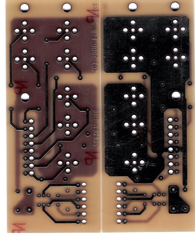
The Output BoardI received the Cardas output jacks Friday which means I was able to finish laying out the board with accurate device footprints. I will probably order a prototype run of the board this Wednesday, when you may see me selling the extras on E-bay if they fit.
I've also ordered all of the parts for it as well, which is just Vishay Mil-Spec Metal Film ultra low noise resistors. Everything else I will be pulling off the original board.
The Power SupplyWhen I bought the Tandberg 3001 tuner, I was informed something smoked, and when I took the cover off and found that in the power supply at least one cap had expanded beyond it's normal physical dimensions as well as a carbonized trimmer pot. In addition, I read in a Yahoo FM Tuner group that the power resistors were standard cement types, and sure enough mine were too.
As most of you know, electrolytic caps do have a limited shelf life, and are often the first to go in electronics gear, often taking out other components around them. So for the PS, I ordered abox full of Panasonic FM and FC capacitors, Kiwame Carbon Film and Vishay Metal Oxide resistors, new trimmer pots, and bags full of Panasonic Metal Film caps to use for bypassing. There will probably be a need for new transistors as well, but taking each one out and testing it would not be easy. Instead I will replace all the caps first, and then see if I can diagnose any bad transistors. After this, I will replace the trimmer pots, and power resistors.
Ok, before anyone starts, there is just no space in this thing for the fancy Solen/Auralcap/Multicap bypass caps that are all the rage so don't even start with me. If you aren't going to get hot without those, scroll down and droll at the CJ Power supply mods, then come back to this project. :) Maybe when I start making power supply boards for the 3001 from scratch we can discuss these. :) Just kidding, there's no way I have time for this with work and school. However, if you are a well-heeled devotee of the 3001 and really want a custom built power supply board with some seriously upgraded capabilities and components, send me a note. :) Maybe I can make a bunch of them at once.
Ok, so why not some Black Gate caps? Mostly, they have too long of a burn in time which starts over when you turn the unit off. According to what I read, it takes days for their electrolyte to become fully saturated and for you to get the full BG experience. With a vintage piece of gear like this with notorious overheating problems I just felt that BG's would not be worth the cost of ownership. I'm not going to leave it turned on for more than a day or weekend at a time. Besides, the Panasonic FM's are really really good compared to what was in there originally when this tuner was dominating the FM tuner ratings. Lastly, frankly, I need to see if this tuner ever turns on again. The power supply smoking may have ruined it, in which case spending a couple of hundred bucks on PS caps would be a complete waste.
On Progress and Humility FYI, this tuner is going to rock when I am done, but honestly, if I had to design this tuner from scratch, there is NO way I could come close to the achievements Mr. Tandberg made to Audio, so I want to take a moment and express my gratitude at being able to in a small way connect with the work he and his engineers did in the 80s.
However, it is also true that many things have changed since then, so it is likely that Mr. Tandberg himself would have made improvements in several areas if he were still around. To begin with, double sided circuit boards are much cheaper in both production and prototype quantities. This is one major reason why I will make the amount of imrpovement in the output board that I will. It's worth going over because much that applies to it can apply to many re-builds of vintage equipment. The original board was single sided, forcing the ground plane had to share space with the audio traces. Because my version is double sided I can put down a massive ground plane on one side, with the signal traces on the other, which gives me better spacing which should lead to lower crosstalk and lower noise than the originals. The other reason this version will be better are the connectors. Rhodium over silver over brass will beat tin over plastic almost every time. As I noted above, I'm using very low noise Vishay resistors on the board as well. Lastly, I'm adding a surprise to the board specifically for that rare breed, the FM and cable junkie. He's not an average audiophile, nor is he an average cable head either. This species of audiophile still tries to find an FM station worth listening to AND he's a cable junkie. A very rare combination, usually found around Boston or LA or Chicago. But I won't say more until the boards are back. :)
The next place where things have gotten better than the Tandberg (and frankly, MY) days is in the size and quality of components. Electrolytic capacitors as well as power resistors have made major improvements in their quality as well as their size. A half watt or 5 watt resistor is much smaller than it used to be. Also, you can find some very high power resistors in metal film versions, which can take 30 watts in the space of a TO-220 case. High power, high stability and low noise in small packages. Sadly I can't use them without redesigning the power supply board (hah!) so I'm going to have to "settle" for some Kiwame's and Metal Oxides. But still, they are SO much smaller than their originals it's almost hard to use them. Two watt 1.2 Ohm Metal Oxide resistors are so small these days it may be difficult to put them in the place where the 2 1/2" long resistor went originally.
Also, we now have the ability to get very low inductance electrolytic capacitors in smaller packages than what Mr. Tandberg used as "standard." I'm talking about the Panasonic FM series here. They are smaller, have something like half the impedance of most other low inductance electrolytics when compared to Nichicon low impedance types. The one bit of a drag is that I can only find them with values up to 50V, so you have to step down to Panasonic FC types to get 63V caps. Not a big deal if you can apply some under-the-board metalized polyester film caps to make up for this small shortcoming.
My point to all of this is that I think if Mr. Tandberg had been succesful, and was still around, I think he would be designing with:
- Double sided boards
- Smaller, higher quaility components which....
- Would let him get enough space for things like metal film resistors with heat sinks, bypass caps, larger ground planes and traces, along with holes in the board for the transistor and resistor heat sinks.
One of the things I've noticed about the 3001 is that I don't think I have ever owned a component so full of parts. I think this tuner has more parts than all of my other audio components put together. Putting together this many parts, on so many circuit boards using single sided technology in a low profile design really was an amazing bit of work. If I were to do the industrial design for gear like this I would have used a card cage design, and have made it twice as tall. This is closer to what Revox did during the same era, making their products easy to service but looking a bit like ham radios or toasters by comparison.
When I post again I'll put pictures of the insides of the Tandberg 3001 so you can see what I'm talking about when I say "full of parts."
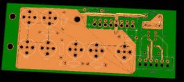 123 Layout from Sunstone. The software is among the best that I have used in the free or try before you buy category. It turns out that Sunstone is the parent company for Express PCB, which also has a free PCB layout package. Frankly, it's easier to use, but I went with this one in order to be able to order boards with more features, like 2.5 oz. copper, silver plating, etc.

 Goodwins for $275. Now, if you are any sort of FM fan at all you know that a 3001 doesn't sell for less than $700 anywhere unless there is something wrong with it.
