Sunday, February 14, 2016

The LM-1 Bookshelf Version

The LM-1 speakers are part of the Leach Memorial speaker project, started here. 

Introduction

The LM-1 is a small, two-way speaker kit using a 1" ring radiator and 5 1/4" woven fiberglass mid-woofer specifically designed to be placed on a bookshelf or desk. Because of these choices, on a bookshelf, the frequency response is smooth and extended with real output between 40Hz and 30kHz and is unusually efficient. It is suitable for high quality music production, desktop or home theater use as either main or surround speakers.

The LM-1 is also quite friendly to flea-powered digital amplifiers. 

The final cost to build is estimated at between $240 to $470 a pair depending on whether you build or buy the cabinets and the crossover parts you choose. Each speaker is approximately 12" H x 7.5" W x 10" D.

Background

One famous speaker design to come out of Dr. Leach's laboratory was a small 2 way design by a graduate student named Kirk Wrzesien which was published in 1990.  As stated, the goal was:

..to design a premium 2-way loudspeaker system for a small dorm stereo system and for use as rear loudspeakers in a home surround sound system

While the design was pretty popular, especially along engineering students, the parts are no longer available, so 26 years after the original design the time for a refresh has arrived.

In addition to the ageing of the original design we're now living in an era where advanced measurement, design and simulation tools are within the reach of many hobbyists, allowing us to access much of the same resources Kirk and Dave would have had at GA Tech in 1990. This let's us re-imagine the original design with modern drivers, as well as share the tools and techniques to any who wish to learn.

With similar goals in mind, but with no obligation to replicate the original design's frequency response identically I will add a few requirements to my poor ode and attempt to show how this can be done by most DIY'ers with a few tools.

  • Sounds best on a bookshelf or desktop. I have to assume dorms don't have room for speaker stands!
  • Is inexpensive enough for a graduate student to afford (under $500/pair including cabinets)
  • Has a very simple crossover design
  • Can be used for the front and rear surround speakers
  • Try to stay true to the brands used by previous designs that have come out of the GA Tech audio laboratory.  
  • Has a neutral, versatile, musical sound free of deliberate sweetening gimmicks. 

Output will be limited, as you would expect from a small, high quality monitor. Mate them with a subwoofer crossed over at 60 to 80 Hz and you'll have an outstanding full-range system.  It's not an exaggeration to say the parts chosen for the LM-1 would justify a store price of around $1,500 / pair or more depending on the brand name used. See my blog entry here about high-end speaker pricing.

The Design Documents

The part list

Mechanical drawings for the cabinet and port

Electrical Schematic

Electro-acoustic measurements

Tools used for the electro-acoustic measurements

Crossover simulation files and discussion

XSim Crossover Simulation Software


Search Engine Helpful Strings

Just some text to help search engines direct here.Some builders may be looking for similar items.


Physical Layout of Coils and Capacitors in Speaker Crossovers

Here are some completely free tips on laying out a passive crossover. Regardless of whether you use point to point wiring, an off-the-shelf board or like me, like to create custom PCB's for your works of art, these tips will help you get the best sounding and most reliable results.

Saturday, February 13, 2016

LM-1 Testing Driver Distances

Distance Assessment via Interferometry

Sounds fancy, doesn't it? The first step for me in crossover design is to measure the acoustic distance between the drivers in the cabinet. What? You don't do this? You never heard of this? This information is key to any good crossover.


Prior Art

In 2011 Jeff Bagby documented a procedure from which this work may be derived, though not knowingly. He might even be it's inventor. I encourage you to read up on it here and at least give him the credit he's due for helping the DIY community. As I learn more about the provenance of this procedure I'll gladly update this document to give credit where due.

I learned this technique by reading some tips online and experimenting myself, and a result all of the writing, measurements, pictures and errors here are my own and written without the benefit of his paper.


The Procedure

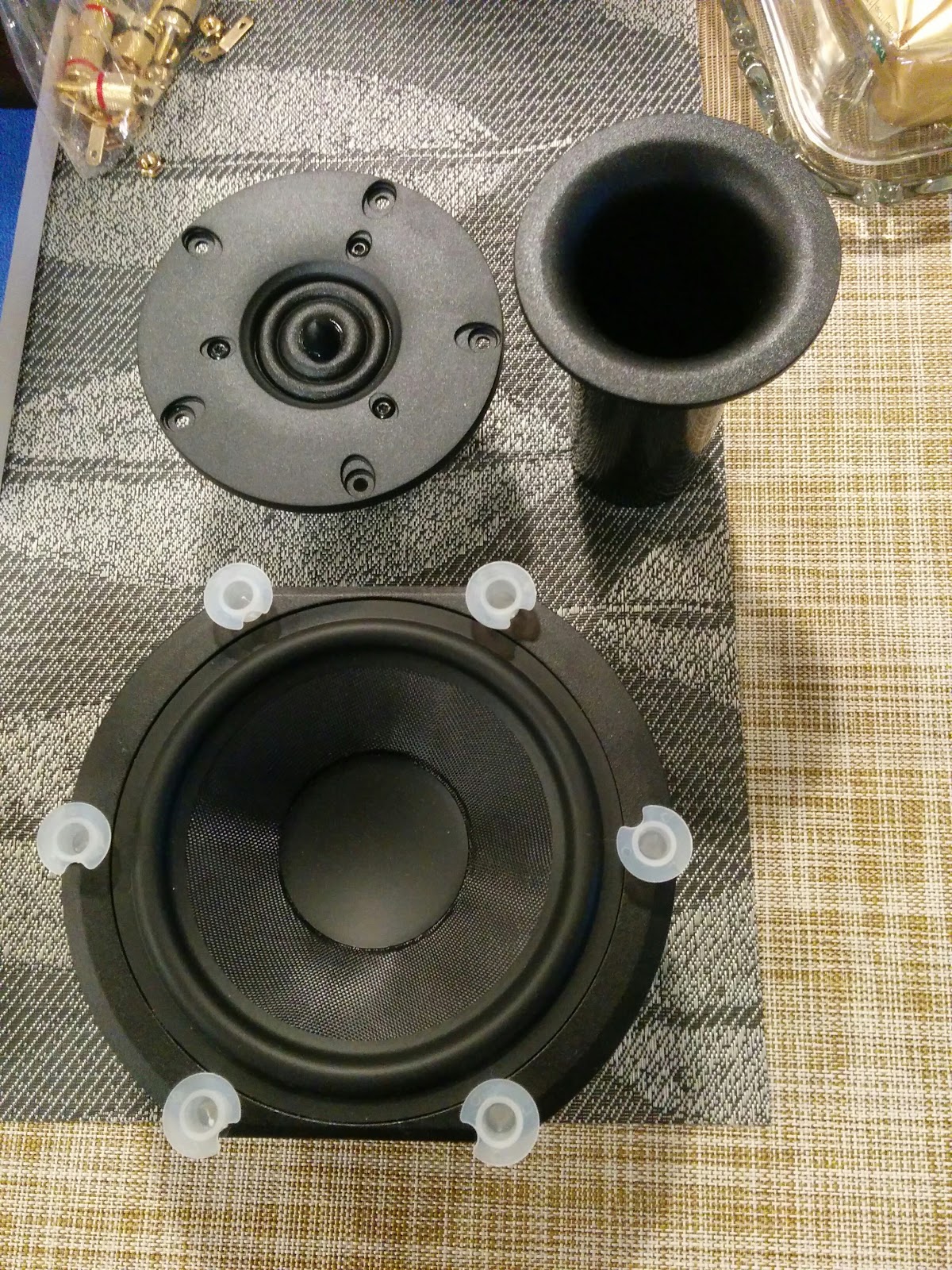
First, build a test baffle. The actual size or even if it's really a cabinet or not is up to you.  The important part is that the drivers have the same distance from each other and from the listening location. So, if you are building a box with a flat baffle like we are, you could use a single sheet of plywood for your testing assuming it was thick enough to inset  properly or you could use the actual cabinet, like I did.

As you can see I attempted to inset the odd shaped peerless woofer and it's ugly. Maybe not so much if I had painted it. Anyway, point is, the drivers are placed in the cabinet at the correct location and inset depth. 

The goal is to get the correct acoustic distance between the two drivers so when we design the crossover the simulation has the correct phase information to calculate the correct frequency response.


The Test Setup

You'll need a measurement microphone, 3' (approximately 1meter) from the listening axis. From the beginning to the end of these steps you must not move either the speaker or the microphone at all. Any movement will throw off the results. The listening axis is usually the tweeter, but some makers prefer it to be the woofer, the pro's and con's are beyond our work here. If you see a speaker with the tweeter below the woofer you'll know how they had to go about measuring though.

Believe it or not, a calibrated microphone is not needed for these tests.  Any microphone that is relatively accurate and covers the range of the tweeter (more or less) will do.

You may use a 10 to 20uF capacitor on the tweeter if you so desire to protect it from bass. 10uF is large enough that it won't affect the areas we care about much. 20uF is even better. :)   The more expensive the tweeter the more delicate they tend to be so study the tweeter's requirements carefully.

Here is a schematic with a 10uF capacitor protecting the tweeter, S1. Of course, during testing you'll need to decide which driver to leave connected or not.

This test signal does not need to be very loud.  A test signal that is 70 dB or more at 3' is fine. That should be well above the noise floor of your measuring room.

If you are analyzing an existing loudspeaker  you must ensure you  have removed any existing crossover components from the circuit.  


The Tools

 The tools we'll be using for this excursion are the following:
  • OmniMic - Published by Dayton Audio, authored by Bill Waslo. Inexpensive speaker measurement system for beginners to intermediary users. Everything from FR, phase, distortion, waterfalls. Comes with calibrated microphone.
  • XSim - Free Crossover design and simulation tool from Bill Waslo
You do not need any of them to build the LM-1 as we'll be giving you the complete results and schematics. However if you wish to do what is shown you'll need some version of these tools.

Data files suitable for XSim have been posted to Google drive here. 


The Measurements

Of course, for all of my testing I'm using OmniMic  but any test tool that can export an FRD file to XSim is fine. In no particular order, measure:

  • The woofer alone
  • The tweeter alone (or with a cap to protect it) 
  • The woofer and tweeter (if you use a cap to protect the tweeter use it again here)
Save each of these measurements to a separate FRD file. In case you end up re-using the files in crossover design, make sure you click the "Show phase" checkbox.


Inference

Inference is the technique of discovery when you cannot measure or know a particular data point directly. For instance, if you touch a door knob and it's very hot, you can infer there is a fire on the other side of the door. What we're doing is much safer than that!

We will infer the distance based on how the delays of the acoustic centers affects the combined frequency response. The fixed difference in time and distance between the drivers we are measuring will cause varying amounts of phase changes across the frequency spectrum. These phase changes cause a unique set of destructive and constructive interference. These changes occur at no other distance but this particular one. This is in effect a finger print of the distance.

With the three FRD files collected,  create a schematic in XSim to represent the woofer and tweeter together. Do NOT include the tweeter capacitor or any other crossover component in your schematic for interferometry.

Import the FRD file with the combined tweeter and woofer responses in the Frequency Response window on the right. Here you see the actuual measured Frequency Response plot of the combined output in red, as well as the simulation's output in blue for the LM-1.


See how poorly the simulation's FR chart matches the actual measured response around 5 kHz? That's what we want to improve. It's mismatched because XSim doesn't have the correct distance to predict the correct destructive interference at 5kHz, or many other places either.

Usually woofers are at least 1" behind the tweeter, so "Tune" S2, and set the "mod delay" to 1.0" as a starting point.  Increase the delay slowly until the two frequency charts match from 5kHz upwards. Like this:


For the LM-1 prototypes this happens at about 1.32".

I've decided to surface mount the woofers, so I will need to re-measure when the new baffles show up but this exercise shows you exactly how to calculate the distances you would need to proceed to actual crossover design.

In the next posts we'll cover different theories of measuring speaker drivers, as well as show examples.

Do Not Panic!

At this point you may be thinking to yourself "Those are horrible looking graphs! This speaker is going to suck!" Not true.  Look at this example.  I used the same speaker drivers, but measured in a real book case.  See how the crossover improves the results?


By the end of this arc we'll be pretty close to that, not anywhere near the graphs we used for speaker measurements, so take some deep breaths and go massage your brain, it's worked hard! 


Crossover Basics

Links in the Series:

https://speakermakersjourney.blogspot.com/2016/02/crossover-basics.html

https://speakermakersjourney.blogspot.com/2016/12/crossover-basics-impedance.html

https://speakermakersjourney.blogspot.com/2016/12/crossover-basics-driver-response.html

https://speakermakersjourney.blogspot.com/2016/12/crossover-basics-zobel_8.html


 Introduction

This is a very simple introduction for non-engineering students who want to learn about the electronic parts that make up a speaker system. Math is not forgotten, it is deliberately excluded from this posting to give the budding speaker designer an easy introduction into the range of topics that go into speaker crossover networks and their design. It's by no means intended to be a canonical reference, but rather a tasty first meal. My hope is that readers whose interest remain piqued after reading this will be much more willing to learn the math that underpins crossover design as opposed to being overwhelmed by it.


Drivers

A speaker driver is the moving motor in a speaker. It is what takes electrical power on two inputs and on the other side produces sound. Most high quality modern speakers have drivers of different sizes. That's because no one driver can handle every note.  Much like an orchestra, or a band.  The lower the note, the bigger the driver. The higher the note, the smaller. At the very least a speaker will have a tweeter for the high notes and a woofer for the bass.

There are of course single-driver (i.e. Full-Range) speakers used by cheap electronics manufacturers as well as boutique makers which do not use crossovers at all. They are out of scope for this post.

Crossover Parts

The two most common parts in a crossover are capacitors and inductors. Think of them like bouncers.  More rare, and much simpler are resistors. In general they behave like this:

  • Capacitors (antiquated term: condenser) pass high frequencies, and block low.
  • Inductors, a.k.a. as "coils" pass low frequencies and block high.
  • Resistors block (or resist) all signals equally

The last part that is commonly used is a resistor.  Resistors resist the flow of current, hopefully evenly at all frequencies. Another way to think of them is that they take voltage away from other components by using it for themselves.

Also keep in mind that the term "block" here is not an absolute firewall. When we say capacitors block low frequencies, the amount they block varies by frequency.  This is why Farads matter.  The same for coils.  The mH give us an indication of just how much they will block at each frequency we care about. A better word than block might be "slow" or "limit."

Simple Crossover

Now that we've discussed the parts you'll need to be familiar with, let's take a look at a schematic. We'll use XSim to create our images and charts. It's a free tool created by Bill Waslo, a regular at the DIY forums and the author of OmniMic. I encourage you to get your free copy of XSim here and follow along with the examples.

Schematics are engineering maps to how electricity should flow in a circuit. The image above shows a schematic using the simplest possible crossovers on a tweeter (S1) and woofer (S2). The capacitor is shown as C1, the inductor is L1. The triangle is the ground.  The ground symbol is a type of short hand to show that they are all connected together.  Crossovers can get far more complicated than this, but for mods it won't matter to you.  (queue evil laughter)

The confusing part for beginners is that a schematic does not show the physical relationship of the parts, or their physical size either.  All we can see here is the electrical values.  After reading this blog you'll want to examine a physical crossover and see if you can identify the pathways to each driver yourself.

The parts here, C1 and L1, are connected in series with the drivers.  That is, electricity must flow from one to the other. We can use XSim's Frequency Response Plot to show how the parts are working together.


The black line is the electro-acoustical sum of the effects of the speaker drivers plus the crossovers.You can see the tweeter's new response in red.  Now the tweeter response, instead of being ideal (impossible in the real world),  slopes upwards until 1kHz at a rate of 6dB/octave. For the woofer, in yellow, the coil causes a complementary effect. The woofer response now slopes downwards at a rate of 6dB/octave after 1kHz.

We call the 1 kHz bend the "knee" of the curve. this is where the rate changes from it's normal slope (6/12/18 dB per octave) to asymptotically approaching flat. At it's flattest is where our filters have ceased to do anything useful.


Second Order High Pass Filter

Let's take a look at a more complicated schematic, where we will add parallel components.  In this example we've added L2, which is said to be parallel to the tweeter.

You should also be aware that you may have multiple parts in series.  That is, you may have C1, L2, and then C2 in the tweeter section. That's pretty common.  Woofer and midrange drivers may also have multiple parts. We'll cover this more below under "What's the Difference?"

The last thing to do is show a resistor.  Often designers have to work with parts that don't match up completely in terms of voltage sensitivity.  That is, one driver will naturally be louder than another. They fix this with resistors, and commonly use an L-pad to maintain the correct driver impedance while changing the volume of the driver.  Here is just such an example.

R1 and R2 make up the L-pad we were discussing, so named because of the shape it takes in the schematic.  Since R2 is parallel with the driver it reduces the apparent resistance of the tweeter, which may save money.  That's a more advanced topic. The crossover designer may use just a series resistor as an alternative design, and it's a perfectly valid approach depending on the other components of the circuit.

What's the Difference?

We are adding "poles" to the design.  That is, we are adding parts which add 6dB/octave of slope with each part. Consider this example, with three identical ideal drivers. Each driver has a different 1kHz high-pass filter between it and the amplifier.  Of course, no one should actually build a speaker with 3 drivers like this! It's just for illustration:

 
As you have hopefully guessed, S1 uses a first order, S2 a second order and S3 a third order high-pass filter. You can see how the slope of the crossover changes as the poles are added below:


As the order (number of poles) of the filter gets higher, the slope gets steeper. The normal slope for first, second and third order  filters is 6 dB, 12 dB and 18 dB per octave, or 6 dB x filter order. I say "normal" because after the first order, you can play somewhat with the bump and final filter slope.  If you notice here, the second and third order filters start to develop a bit of a bump before rolling downwards.  This is out of scope of our discussions here, just know that the filter order are general terms, not absolutes.


Low Pass Filter Examples

 Now that you are familiar with the idea of filter order and poles, let's show you the same idea only using low pass filters instead, again with a knee on 1 kHz and ideal 8 Ohm drivers.


Notice that the order of the coils and caps is now reversed, but the number of the parts is consistent. As you can see, coils and caps while not mirror images of each other, are complementary. That coils and capacitors exist is proof enough to me that if there is any divine influence on the physics of this world then that divine presence intends for us to listen to good music for all of our lives. The slopes and phase angle changes for low pass filters are what we described before. 6dB, 12dB and 18 dB for first, second and third order filters, respectively but sloping in a different direction.


Before You Leave

It's important to note that throughout this post we've been using  "ideal" drivers with exactly 8 Ohms of resistance and a flat, infinitely wide frequency response. In the real world speakers are not flat. Every real world loud speaker driver ever made is actually a type of band-pass device, with upper and lower limits. The effects of the crossover slopes are additive to the frequency response of the driver, not independent of them. We'll cover that topic more in the future.

Congratulations! You now know some basic ideas about speaker crossovers:

  • The components that make up a passive crossover
  • Why we use crossovers in speaker designs
  • How schematics are used to draw them
  • XSim to design and simulate crossovers
  • How to identify different crossover orders/poles. 
  • How the order of a filter affects the frequency response
  • How L-Pads and resistors in general are used to match the levels of different drivers. 

Additional Resources


Thursday, February 4, 2016

The LM-1 Driver Locations

Living in an apartment I don't really have a chance to build my own cabinets, so I relied on cabinets from Dayton Audio. For the satellites I'll be using a version of these:


Dayton Audio TW-0.25CH, $175/pair or their curved-side brethren. I like the square sided cabinets as it makes it easier to place the speakers on their sides.

Update: September 2016: It seems the straight sided cabs are gone and only the curved TWC-0.25 versions remain.

Of course, you can save the $220 for the cabinets by making them yourself. You will need to maintain the front baffle dimensions (7.5" x 12") as well as inner volume of around 0.3 cubic feet for the tuning to remain accurate.


It's been too long since I touched a CAD program. I would really date myself if I explained which program I liked the most.  So instead, you get to see my hand-drawn artwork here! Rejoice.


Measure Twice, Cut Once

It's always good to do a full-size mock-up if you can, and given the size of the front panels this was straightforward. Please note that to make the pictures more interesting I've turned some of them around.

The LM-1 speakers are meant to be listened to in a traditional, tweeter over woofer arrangement. They will also play horizontally, if necessary but it's not my intention to make these speakers "landscape mode."  It's just me being a little creative with the camera.

After locating all the important points, I placed the drivers on the paper to visually inspect the resulting design.


Note that the tweeter is in fact offset. This should reduce edge diffraction. You may center it instead, but you MUST maintain the driver distances. This means two things. The driver to driver distance as seen to the right, but also how the drivers are mounted. If you move either driver towards or away from the listener you throw off the perfect crossover integration.


I have hand drawn the driver locations.  As you would expect, the woofer is centered across the vertical axis, and I've tried to maintain equal spacing to the left of the woofer and to the right of the tweeter. You could probably center the tweeter instead and it would be fine.

Measurements are taken from the closest corner.

I also measured the distance from the edge of the baffle to the flat side of the woofer.  I'll use this to put masking tape down before routing the outer diameter of the driver.

Despite the woodworking being quite limited, there's still going to be quite a bit for me to do.  I'll need to drill pilot holes, measure, decide if I really want to add stuffing or a port, re-measure. There's a lot to do before I can really get down to the business of crossover design.


Woofer Mounting

There is no doubt that flush mounting provides the best measured sound due to the minimization of diffraction effects from the sound coming off the driver ring and hitting the cabinet front. However, cutting these drivers in is a real pain so I have surface mounted them instead.

Inner Chamfer

You must chamfer or round-over the inside of the woofer holes. The Dayton cabinet faces are an inch thick, more than enough to block most of the back of the woofer basket.  Of course, this is not needed acoustically for the tweeter, but I may do so just to make it easier to get to the terminals.

Outer Chamfer  

The Dayton baffle has a round-over on the edges that is about 1/2" round. If you build your own you should strive for a round-over or chamfer as well to reduce edge diffraction effects.

Bass Reflex Port

After much useless soul searching, I did finally include a bass reflex port in mine. 1 1/2" and 4" long gives us a very useful -3 dB point around 55 Hz. Not a boom box, but very useful with a subwoofer crossed over anywhere between 50 to 90 Hz.  Locate it directly behind the tweeter.

Must you port? No, you don't have to. You can also seal the port after including it, but you'll loose about 20-30 Hz in low end response.  If you are OK with about an 80 Hz -3 dB point then you can leave the port out. This may be a better option if you are absolutely sure you will only run the speakers with a subwoofer, as the maximum excursion will be better controlled, and you'll get more maximum output. Meh. Really not worth a lot of thought. The point is, ported or not the crossover stays the same.

Padding

Sonic Barrier

Experience has shown that the majority of vibrations in Dayton cabinets happens in the front section, before the middle brace, so cut the Sonic Barrier and coat all 4 sides of the front with it. The Sonic Barrier will also help increase the apparent cabinet size, so we get a few extra Hz of bass extension.

For the rear, cover the back wall with Acousta-Stuf (or similar), and stuff a little into the sides.  If you don't do this you'll get a little extra boom from the speakers.