We often read or think about crossovers as being one dimensional tools and only there to ensure a smooth (maybe not flat) frequency response in a multi-way speaker. Truthfully the interaction between the crossover and the drivers has several more dimensions:
- Distortion
- Dispersion
- Impedance
- Dynamic range
- Voicing
Frequency vs. Dispersion
All drivers have a limitation in dispersion related to their width. As frequency goes up the driver output narrows geometrically. This is an unavoidable result of physics. The exact manner and shape of this relationship can be complicated but the basic issue has to do with the length of a wavelength vs. the width of a driver. As frequency goes up the wavelength decreases and the shape of the output goes from hemispherical to flat. At 3,000 Hz the wavelength is about 4.5", not so coincidentally the width of the midrange driver we'll examine and the low-pass crossover point we've set for it.
The Sample Driver
For this article we'll focus on the first two, distortion and dispersion. Think of dispersion as the off-axis frequency response. To illustrate the issues we'll use a famous high-end midrange from ScanSpeak, the 4.5" Illuminator 12mu/8731T so we can get very specific. Because I recently used it in a center channel build I'm confident in the data as well as the final results. A midrange requires both high and low-pass filters so it's the ideal single driver to discuss distortion and dispersion.
It's important to note that not all good speakers have to have the same goals in mind. For the center channel I built I wanted to have extremely wide dispersion, very low distortion at high volume, in other words high dynamic range.
To over simplify the process, dispersion sets the low pass filter limit (3kHz) while distortion is going to set the high pass filter point (350 Hz).
Dispersion
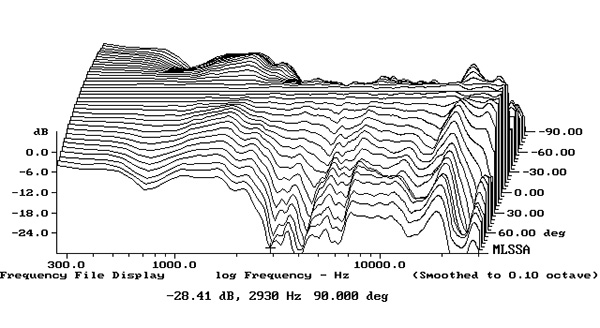
Dispersion refers to how well a speaker maintains it's on-axis frequency response when you are not sitting right in front of it with the driver pointed right at your head. The goal of the speaker designer is to match each driver's dispersion characteristics so that it blends in smoothly with the next driver up. This is notoriously difficult to do with a 2 way speaker so we'll take a look at the
Stereophile measurements for a DeVore Fitdelity Orangutan O/Baby but please note that the response is actually very good until about 30 degrees off axis:
See the dip around 3 kHz to 7 kHz? That's exactly what we want to avoid.
Lets take a look at the midrange frequency response specs, below so we can talk about how we avoided this as much as possible in the center speaker. I've drawn a thick black line at 3 kHz, the crossover point I ended up using.
The green line represents the frequency response 30 degrees off-axis. Notice that it's only 2 dB lower than the on-axis response. By 5 kHz the gap has widened significantly, and the response is getting less than ideal, which brings us to an important point: Limited dispersion is a high frequency problem for each driver, not a low frequency problem. Below 1 kHz there is no apparent difference in dispersion at all. The tweeter and woofer will follow this same pattern.
Distortion
OK, so this midrange has usable output down to 100 Hz, should we use it? This happens to be a problem for almost all speakers. For the answer to this question we'll have to rely on data from the now archived Zaph Audio website:
The black line is set to the high pass filter for this driver, around 350 Hz. Take a look at how quickly distortion is rising below here. Rising distortion as the frequency drops is normal behavior for all drivers and is why the idea of using many small drivers for bass is not actually a very good idea. Too much distortion.
We could, in theory, extend the midrange response down to 200 Hz or so, but why bother? The woofers have excellent dispersion up to 2 kHz and far lower distortion from 50 to 300 Hz.
Incidentally we happen to have used 3 kHz as the low-pass filter setting which further limits the distortion of the midrange.
The Final Crossover
Luckily, this driver is so smooth it required only Linkwitz-Riley, fourth order filters and no additional EQ besides gain-matching to the other drivers. Phase matching was done via digital delay of the midrange and tweeter.
Lets take a look at the results. In the chart below the red line is 45 degrees horizontally while the black line is 45 degrees ABOVE the face axis.
It looks like choosing 3 kHz was the perfect place as there is no visible effect of transitioning from the tweeter to the midrange. The black line's drop needs some explanation. First, almost no one measures a speaker this high, usually testing is limited to about 20 degrees above axis so this is a punishing measurement. Next, the drop off you see is due to the acoustic offset and not because the midrange is too narrow in it's dispersion. The problem is actually that the midrange dispersion is very wide and is now lagging the tweeter by a large degree.
The Other Drivers
Selecting the crossover points for the midrange is not really done in isolation, we just don't wish to overwhelm you with data, but the same types of analyses are done for the tweeter and woofer. To meet our goals we have to pick all three drivers so that we can maximize dispersion and minimize distortion. The only reason I can pick such convenient points on the midrange is because the other drivers are also excellent and will be working in their own butter zones throughout.

No comments:
Post a Comment