Sunday, September 17, 2006

Maybe I should change the name...

of this blog, because I'm so far away from working on power conditioning that it's almost not funny. Instead I've been busy working on my own mini-system, finding ways to improve it one way or another. I've been looking for a good vintage tuner and DAC to put into my CJ/Sumo/Monitor Audio system, and came across at Tandberg 3001 at Goodwins for $275. Now, if you are any sort of FM fan at all you know that a 3001 doesn't sell for less than $700 anywhere unless there is something wrong with it.

So, I went to Goodwin's and got the answer. Aparently this unit came out of some well heeled accumulator (as opposed to collector) of audio gear. The output board was "cracked" and parts in the power supply "assumed their gaseous state." So, I offered him $200 and walked out with it.

Here is a picture of the output board. It's not really as bad as described. The problem is two fold. It seems like a previous owner used really high pressure connectors and pushed so hard on the RCA jacks that it pulled the tabs and the copper off the PCB on the back. The other problem is that these jacks are just tin and plastic.

So, I am left with a couple of choices, I could scrape off some solder mask, and add big gobs of solder, and stick it back in, and start working on the power supply OR I could make a new PCB board sized for Cardas RCA jacks. Well, if you've followed my blog at all, you know which of these two choices I'm going to take. :)

The mechanical drawing of the original board has been completed, now I'm debating which PCB manufacturer to go with. I like the software that Express PCB offers, but I may want options, like thicker copper traces, or gold plating in case I find others who would like to upgrade their Tandberg 3001 or 3001A boards. Posted by Picasa

Wednesday, August 16, 2006

The Conrad Johnson PV-Erik

Here is another picture, this time from behind, and with all of the wires in place.

There are several major changes. In the front (top of the pic), where the Necromonger heat sink is, the original power supply was upgraded to produce 360V, at 1A if needed.

To the right are the dual mono supplies that take the 360 V and feed each tube 330 independently. Towards the back you can see the red and blue wires (red for Right, of course!) which feed each tube independently, as well as a better picture of the Azuma sockets. I was able to take advantage of unused component holes for these, all I did was enlarge them slightly so I would be able to use enough of the wire to get a solid connection.

The wiring is all Cardas 14 ga. Litz copper wiring. Most of the solder was Cardas, but I admit that some of it, especially for the diodes and resistors, was just Radio Shack silver content solder. I just couldn't wait for the shipment from the Parts Connection to arrive. All resistors are metal film, but not particularly high quality. I did get some Dale/Vishay resistors from Mouser, which were only $0.30 each for the 18k coupling resistor.

The two black wires carry the 360 V from the original regulator stage to the two new stages. There is only one ground wire. This was mostly caused by the fact that I had a really hard time soldering 14 ga. wires with a 40 watt soldering gun. I eventually got the knack of it, but for now, this is how it will have to be. The PCB was designed for this from the start, and will help keep the star grounding method of the original board. Posted by Picasa

Thursday, August 10, 2006

Recognize Me?

Tell me honestly, it's not that easy to tell that you are looking at the insides of a PV-10 now is it? Some day some one is going to make a living restoring these things, and they are going to open this up and go "what the f****??!!"  Posted by Picasa

Tubes in a Shroud

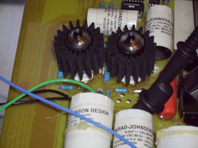
While I was ordering parts from the Parts Connexion I also went ahead and got some upgrades for the tubes. What you are looking at are the 12AU7's in Perl tube coolers. In case you are wondering, yes, they really do remove a lot of heat from the tube itself. Whether that will have any benefit at all in the long run, I have no direct experience.

If you look carefully you'll also see the white of the new sockets peeking out. These are Azuma ceramic sockets with gold plated pins. As far as I know, these were the best sockets I could find which could be made to fit. They come with a gold plated pin in the center. Fortunately a little time with a hand drill and they pop right off, leaving the rest of the socket in perfect condition.
Some Tube-o-philes prefer the brown resin sockets which were original with the preamp. They think it's microphonics are the best, and the contacts are good enough. I looked at the contacts, they looked nasty. I'm sorry, they were going. If I every decide to worry about microphonics, that's what the tube coolers will do. Posted by Picasa

Droolicious caps!

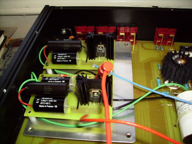
The boards are now fully assembled, and I managed to figure out a way to mount them that didn't violate the fundamental laws of physics. Take a look! Each board has a pair of 3.9 uF Solens and a single Cardas 0.22uF bypass cap. Also, all the wiring and most of the solder is Cardas as well.  Posted by Picasa

Conrad Johnson Power Supply Evolution

There's an interesting article over at Stereophile which is mostly about the CT5 preamplifier, but it also talks about how they have moved away from multiple regulation stages as they did in the PV-12 and other preamps, to simplify the design.

I still need the first stage to help drop the voltage, becuase I'm still toying with the idea of removing or reducing the resistor between the two storage caps. Also, by doing it this way, I'm adding more storage capacitance than I would otherwise. I've added nearly 16uF to the overall design, 8uF per channel. That's pretty good at 330V!

Tuesday, August 8, 2006

Voltage Regulator Schematics


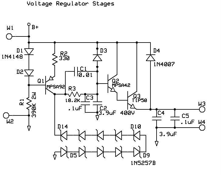
The voltage regulator stages should be familiar to anyone who has worked with Conrad Johnson PV series preamps in the past. The main differences are the output transistor as well as the selection of zener diodes. There is also a difference in the resistor beneath the first diodes, but this value does not seem to be very important. CJ specs 0.15 PS caps for bypass caps which I have been told were made by MultiCap. Frankly, I'm not only running out of room but I wanted to try the Cardas caps in this project, so I'll be using a single 0.22uF Golden Ratio bypass cap across the output filter cap. If I can find enough space for them.