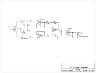
I decided that before going to production with my circuit board design to find a way to simulate the buffer circuit before hand. I found a shareware product called 5Spice which worked pretty well. I couldn't find a way to zoom in on the schematic, but beggars can't be choosers.
I truly long for the days when I worked for companies that could afford to purchase integrated schematic capture, simulation and PCB layout tools. It would have saved me the trouble of drawing the schematic twice, making my own NE5532 models, and then trying to use different keyboard shortcuts in each. Anyway....
Based on the simulation analysis, I realised that because the voltage divider I was using was single ended, the power line signal shape I was seeing in Visual Analyzer were wrong. The neutral line noise was coming in at 1x while the line signal was 1/10x. Also, I didn't like the band pass characteristics I was seeing. Lastly, I realised that part of my problem was that the input impedance was so high that I was going to get much more noise than any real audio equipment would ever see.
So, with this in mind I redesigned the front end. Now, the input is balanced, the input impedance is reduced to around 55K, and the 115/240VAC switch will instead be used to allow me to short the AC line to ground, so I can see the neutral line noise separately. Don't worry, the input impedance will still be 50k, so no more than 3 mA will flow no matter what I do.
Which brings me to a small point about safety. Originally I did not want to shunt any current at all to ground. I was worried about noise on the ground line affecting my measurments as well as concern if the ground wire sould fail. Either in the case or between the case and the service connection. Also, for many reasons, I wanted the signal ground to float. In part it's because PC's have notoriously bad problems with ground loops. However, with the 50K resistors in place on both sides, the peak current that some one could face is 3mA. You'd can feel 1 mA, but 3mA apears to be safe. To put it in perspective, GFCI breakers installed in your kitchen trip at 10mA. 20mA is conisdered potentially lethal, and 16mA is considered the maximum amount of current that can flow through an adult and still be able to let go of the conductor. So based on all of this, I think it is in fact safe to connect the line and neutral to ground at this point.
Not shown in the schematic are 50mA 5x20mm fuses which will be on the hot and neutral side.
Also, I've changed the arrangement of the TVSS diodes. There are now two, and the'll fire at about 15-20 VAC (depending on which I decide to get, finally). This should ensure that even if a failure of the neutral or ground occur the buffer as well as any connected PC or audio equipment will remain safe. If I had more space, I would instead put in a "muting" cirguit like they use in op-amps and amplifiers so that if the voltage at either input of the buffer were too high it would disconnect, but I just don't have the space, and with 50K of input impedance I don't think anyone will be in danger. If my cat pees on it though, all bets are off, but that would be the case if he peed on my 300w/Ch InnerSound amp as well. So, UL be damned! :)
No comments:
Post a Comment