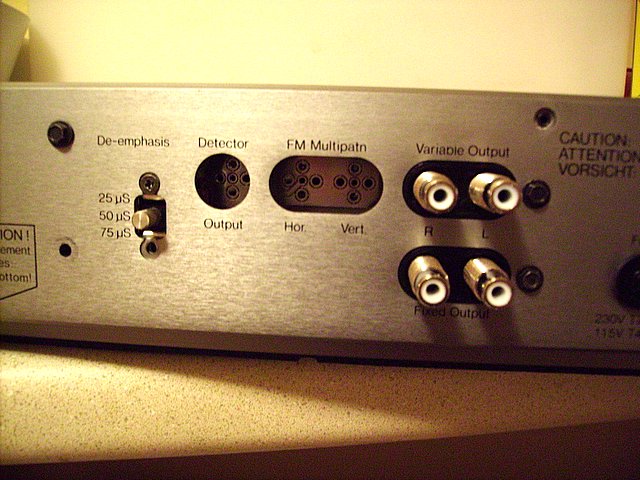
Saturday, October 28, 2006

The Long Way Home


Gentle Reader (and I do mean singular!),

I'm happy to say that the power supply rebuild has all but finished. Let me walk you through the pictures. First, is a picture of the original, unadulterated board.

Notice the large cap in the middle next to the transformer? If it was a can of beans you would have had to throw it out for having expanded beyond it's size. My work was cut out for me.

Replace every electrolytic capacitor and every cement resistor. First job was to remove every single part. Leaving me with a very naked board, like this one.
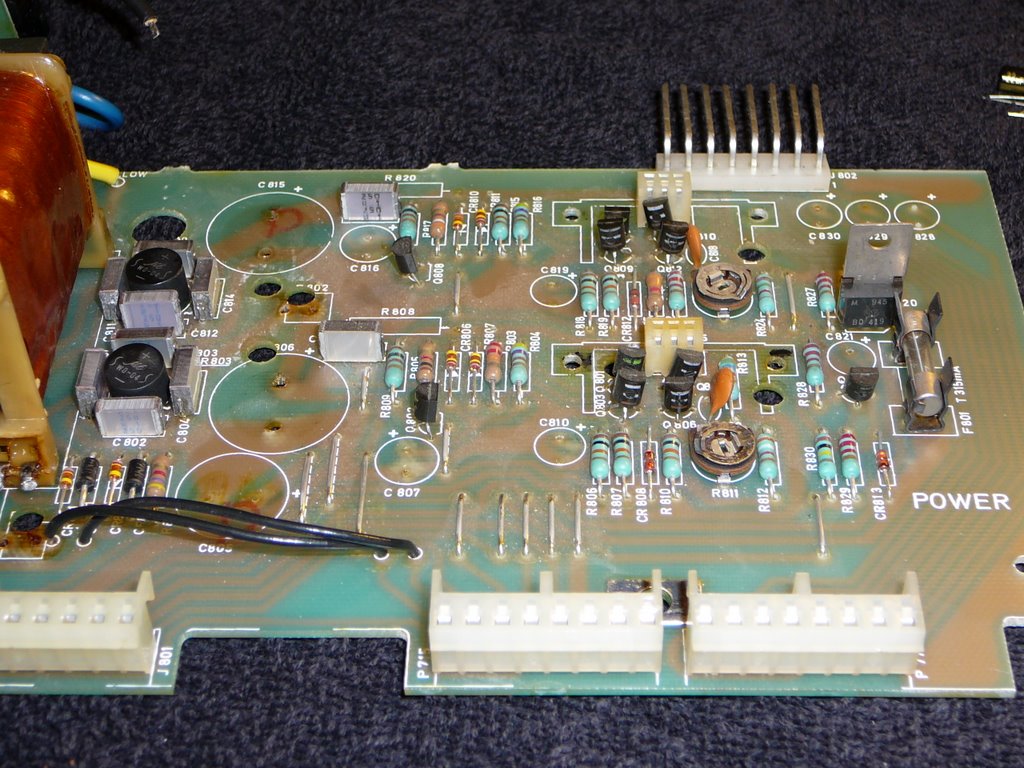
I removed the two main transistors and their heat sinks so I could take better measurements of the circuit board and the holes underneath.

After removing all the parts, I like to add parts back based on the height of the parts. The smallest parts, or those which are closest to the board go in first, then I move my way vertically. This basically meant that the 22uF capacitors went in first, then the power resistors, and then the big filter caps next to the tranformer.

I know it makes me seem old-school to say this, but I really am amazed at how much smaller and better components are today than they were just 10 years ago. Let me show you the finished board to explain.


Look at just how small the caps are compared to the originals. Also, see those tiny black resistors? Believe it or not, they are 5 Watt Mills non-inductive wirewound. You can't get any quieter than this friends, and they are tiny compared to the cement resistors they replace.

You might notice the canary yellow trim-pots which have suddenly apeared too. These are definitely a nice upgrade. The originals were open, carbon composites. These are sealed conductive plastic trim pots. Smooth as honey, electrically quiet, and have much better long term reliability and stability than the originals. Unfortunately one thing I did find when I put everything back together is that the 5V outputs were far too low, which I think is due to a bad transistor. Not a huge deal, but it means the tuner won't be put back together this weekend.

Friday, October 27, 2006

Mid-Terms are Over, Mostly..

Which means, I can take a little break from the world of academics and focus on the power supply. Mikel at the FM Tuner Group suggested I should upgrade one cap to an 80V or better unit, which is on order, but everything else I think I need I have, so Saturday I begin the overaul, and perhaps begin the mechanical drawings on a PS upgrade.

You know, many people whose opinion I respect say that the power supply in the 3001/A is very good, and I mostly agree, but it's not what I would call spectacular. In particular, you have a situation where all of the filter and storage capacitors are on high impedance paths away from the voltage regulation stages. The voltage regulators are kind of live and let live when it comes to all of the different boards they supply. Each board contributes a portion of the overall filtering, but electrically each board is far from the regulators, so sags in the main regulators may take unnecessarily long periods of time to correct. It's all very touchy-feely. Each board can affect all the other boards to some extent.

So, my research is going to be in creating a daughter board to allow the regulator transistors to dominate the output voltages, letting the filtering on the individual boards relax and no longer worry about what the other boards are doing to the supply, and shorten the effective distance between the regulators and the boards themselves. Maybe. I only sold a few of the output boards, so if I do this next step it will be a one off. The good news is that from my initial research I can do it all in a non-destructive manner. I think. Well.....

Thursday, October 19, 2006

Digital Camera Cases

Since my GF has adopted my old digital camera, I bought a new one, and then I went out shopping for a camera cover for it.

I have come to the conclusion that there really is no such thing as a good one.

I bought a Tamrac Neo, which I guess means it's made of neoprene, that stretchy fabric they use in wet suites. I have to tell you all, that it's not designed to protect the camera from anything but dust, scratches and mild finger taps. There is no real cushioning in the case at all. It's just stretchy fabric. I also bought a little case for my Pentax Optio. It fell off the strap of my back pack as I was walking to the train, and it has never been the same since. There was almost no padding in that one either.

So, seriously, Tamrac, what are you, and all your competitors thinking? I can't beleive that it's all that difficult to put some foam, something, anything mroe in these cases. Even shock absorbing jell.

On top of all this, the neo case is actually made much bigger than it needs to be by the ultra wide back which the neoprene is sewn onto. I can but hope that some industrious Chinese textile mill will read this and start producing genuinely protective portable case for digitals.

Thursday, October 12, 2006

Connector Porn

First, a little tease with the shrouds fitted over the jacks, enlarged slightly to fit the threads. The cross resistor is a fix to a problem in the Rev 1.0 boards, which is fixed in 2.0.


Second, a coy shot from the side with the shrouds removed for your viewing fancy.

Naked Cardas jacks, Vishay Dale Resistors and all the other parts an audiophile needs to listen to ensure his listening satisfaction.

Isn't that a lovely thing? Beautiful high performance jacks reflected in a pool of plated copper. Makes the electrons weep to be still.


Lastly, a sadly out of focus picture from behind, the burn marks proof of a poorly trained and inexperienced solder monkey trying to fix a mis- aligned jack.

You really must be sure you put the jacks in straight, because desoldering them after is insanely difficult. I almost gave up and took the board apart.

Real Pics!

Finally, I have pics to show you, my faithful reader (singular, hah!) Take a look at what it looks like installed in the back of my 3001. The missing screws below the switch is because I lost it. The board fit perfectly. More pics shortly. Posted by Picasa

Tuesday, October 10, 2006

It's Your Turn Now

I realise that in part my postings are kind of rambling in lieu of people talking back to me. I haven't gotten a single comment here about the upgrade boards. I have 6 people on e-bay watching to see if the boards will sell, one e-mail asking for 2.0 boards, but no one else really talking to me about what they would like to see, or whether they like the idea or not.

So, if you are reading this blog with interest, please, drop me a comment, tell me what you like, what you are thinking, what you are working on. Are you wanting the 2.0 boards, but want to see if other's will commit first? Do you wonder if modding this venerable tuner is worth the effort now, or are you busy with school and work so you want to upgrade, but not now? What's goin gon?

Thanks!

Reviews are coming? Maybe.

I got a little good news yesterday, a Tandberg owner has asked me to sell two output boards to him to be installed by a well known FM tuner guy. I'm hoping that I can get some feedback from him which I can use to improve any mistakes I haven't caught, as well as encourage other's to purchase the remaining 2 boards or give me reason to make the 2.0 run.

I've also been doodling a PS daughter-card design. I am pretty sure I'll be able to do the PS mod board. It will be either a tweaker's delight, or a perfectionists heaven, adding a great deal of bottom end to the sound, and maybe reduce overal tuner noise, as well as making the PS incredibly reliable, especially with the early models.