Sunday, January 14, 2007

Upgrading the Suzuki

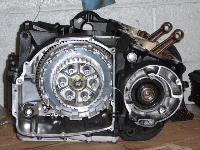
Well, in this case I'm actually downgrading it. At some point around 1989 I acquired a 1978 Yoshimura modified Suzuki GS 1000. It was actually nearly impossible to ride on the street. So I'm having Bikeworx rebuild the engine, repaint it and the frame, and add all the silly things that the DMV requires such as turn signals, horns, that sort of safety nonsense. So for those of you who care, here is a pic of the bottom half of the engine and transmission. With a little luck, when I'm not soldering uber expensive op-amps into inexpensive gear I'll be riding this.  Posted by Picasa

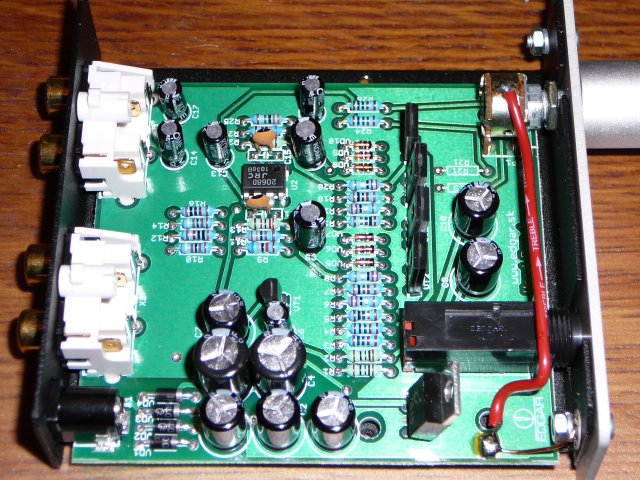
Inside the Pro-Ject Headphone Amplifier

It's only fair that if I show you the insides of the Rega EAR I also show you the insides of the Pro-Ject Mk II. Keep in mind that while the Pro-Ject has more parts in it than the Rega, it's case is half the size. Most of the Rega's ingides is air.

Something I forgot to mention in my last post is that another way in which the build of the Head Box is superior to the EAR is that it uses a double sided board with massive ground and power planes. This means less noise, lower power supply impedance. It also allows the board designer to run direct, short traces from one section to another.

It's clear from looking at the design that the designer worked very hard to keep the audio signal paths optimized, and any radiated EMI from the power supply away from them as much as possible. This is why the power supply caps are crammed in the way they are, and also why there's a mix of 470uF 25V caps and 1,000 uF 16V in there as well. The latter I'm a little worried about, because they are filtering the 15V supply, which gives the caps only about 1V margin of error before they are rated to break down rapidly. A pair of 25 Volt caps would make me feel better about the durability of them. I'll see if I can find some miniatures that will fit. Posted by Picasa

Saturday, January 13, 2007

The Pro-Ject Headphone Amplifier

I'm still looking for good values in headphone amplifiers. As you might recall, I previosly tried the Rega EAR, which was just too expensive and offered too little, and was noisy, so I started looking for something cheap enough that I could leave at work, and maybe give me equal or better value, and maybe be worth modding a little hear and there.

I think I've found it in the Pro-Ject Head Box MKII. The Pro-Ject headphone amplifier has a similar design to the Rega. Meaning, single ended supply, one op-amp driving a discrete amplifier stage. Externally there are two major differences. The price, $99 for the Pro-Ject vs. $299 for the EAR as well as the complete lack of switches on the Head Box. Which I guess makes sense if you are going to put in some BlackGate capacitors that means you'll have to leave the box on all the time anyway. :)

Listening Tests
Right out of the box, the Head Box is significantly quieter than the Rega EAR. I can hear no noise at all except at the loudest setting. It seems to be a little weak on the bass however, and perhaps a little on the treble as well.

Build Quality
The Pro-Ject headphone amp is less expensive than the EAR, but better made, in my opinion. This major difference probably has to do with the power supply filtering. The EAR had about 1,500 uF of filtration, the Head Box around 4,000, with a significant amount of filtration occuring after the voltage regulator.

Just like the EAR, the Pro-Ject amp has to have capacitors at the outputs. They are about half the size of the EAR's so this may account for why I feel the bass just isn't making it all the way through to the headphones.

Future Mods
There are two major areas where you can improve this little box. First is in the capacitors. Replace them all with Panasonic FM's. For the output caps, replace them with 1,000uFs if possible. This should get you some more oomf.

The other area is in the op-amp. There's nothing wrong with the original, but there is nothing great about it either. Socket it and experiment. If you can find an NE5535 to hear what vintage class-A op amps sounded like, I'd recommend it. :)

I'll post as I apply the mods.
Thursday, December 21, 2006

Tandberg 3001 2.0

Ok, just in time for Christmas I am announcing that I plan to do a run of the 2.0 Output boards.

They will include all of the fixes noted in the manual, the biggest being:

  • Crossed resistors in fixed outputs
  • Multipath jack being ever so slightly off
  • One resistor trace being on the wrong side of the board.
Enhancements include:
  • Silver plating instead of tin/lead
  • Fully soldermased and silk screened
  • Thickest available copper thicknesses
Order yours now for $75. Purchasers of the 1.0 boards receive $15 off. Sorry it can't be more, but these things are expensive when you are doing small runs.

Cheers!

Tuesday, December 5, 2006

What DID I get into?

Well, folks, the power supply is fully operational. I wish I could say the same for the tuner.

So long as I'm holding onto the tuning dial, it works great. As soon as I release it, it forgets what station it was last on, and tunes to the highest frequency on the dial.

Also, the presets seem to be broken.

On the plus side, it sounds really great, when I can hold on. :)

So, based on this, I'm going to take it to my favorite Cambridge repair place, Audio Lab to see what Derek can do for me.

Maybe for Christmas.

Sunday, December 3, 2006

RTFM!

Man, if only I had Read the Freaking Manual (R.T.F.M.) a couple of weeks ago I would be listening to the Tandberg instead of griping about upgrading it's power supply.

In the schematic for the Tuning System 2, which is where P801 goes to, pin 1 is clearly an OUTPUT to the power supply. That is, the 5.2 Volts gets generated elsewhere.

I could blame Tandberg, but honestly, had I remembered correctly how a PNP transistor worked, it would have been pretty obvious to me that it was. Fortunately on page 26 there is actually an arrow showing which direction the signal here is going.

What this means is that I really am done with the Power Supply rebuild! Yeay!

With a little luck, next weekend I'll actually be listening to this tuner for the first time!

A fully re-worked power supply with Mills wirewound resistors, and Panasonic FM caps, a slew of upgraded transistors, and a brand new output board with Cardas connectors and Vishay/Dale metal film resistors, this truly is going to be a pretty good piece of gear to own for a few years more. :)

The TDA 3001: Where are all the Parts?

The power supply is back together, and seems to be working. The 5V supply seems to have some sort of remote sense feedback circuit built in. I don't quite get it, but it was driving me mad until I spent some time with a breadboard and tried out different options.

I've finally decided that rather than assume it's broken, I'm just going to put it back into the tuner and see what it does. I need to check the voltages at the 15V and 25V supplies anyway. While cleaning the header pins which connect to the output board I noticed they had ALL come loose. That is, the solder connections were broken on all of the pins. It wasn't falling out, but it would have made a terrible connection. A few minutes with my 100W solder gun and everything was back where it was. I then took out the alcohol and toothbrush and scrubbed the board to get rid of excess flux and any other dirt which might have accumulated while it was waiting in a box.

The one thing I need before I can re-assemble the tuner is a package of insulated quick-disconnect, crimp on spades. A quick trip to Radio Shack, and the tuner should come back in a snap.

Then I'll probably have to worry about the backup battery and the preselect buttons.

You know, I'm almost ready to begin thinking about my next project. After taking apart the Rega EAR headphone amp, I'm thinking I should consider making my own. The one thing the EAR did well was provide discrete output transistors. Unfortunately, their potential was mired by the use of an aging op-amp design, and single ended supply. I am sure making the product as inexpensive as possible played a major part in these decisions. In order to get rid of the output caps you need a double ended supply, and your biasing solution gets more complicated in order to keep the DC offset as low as possible.

So, maybe next I'll make a headphone amp with high quality op-amp front end, with a Class-A discrete output section. I think I may take apart the InnerSound Electrostatic amplifier I have (manuractured by CODA) and try to use their transistors in my design. Yes, it's ridiculous. but that amp sounds soooo good and it's sooo efficient, that at the voltages we need for headphones they may work really well. Instead of 30 devices per output channel I'll use 2 though. But for this semester, this tuner really is all I'm going to be doing. I have a GPA to maintain. :)

Pics will be coming as I begin the re-assmbly process.